GSM A6 FULL KIT WITH LCD & KEYPAD - PIC,8051,AVR ,USB PROGRAMMER,DEVELOPMENT BOARDS - alselectro
Main menu:
- Home
-
GSM/GPS
- GSM/GPS PRODUCTS
- ALL GPS PRODUCTS
- GSM SIM900 RS232
- GSM SIM800L MINI RED
- GSM SIM908 808 GSM WITH GPS
- GSM SIM900A ARDUINO UNO SHIELD
- GPS UBLOX USB with Patch Antenna
- GPS UBLOX RS232 with Patch Antenna
- GSM900 TTL
- GSM MOTOR CONTROL
- GSM A6 BOARD
- GSM A6 FULL KIT WITH LCD & KEYPAD
- GSM SIM800A WITH GPRS
- GSM SHIELD SIM800A FOR ARDUINO
- GPS SIM28 WITH EXTERNAL ANTENNA
- GSM BASED RELAY CONTROL
- GSM BASED SECURITY SYSTEM
- GSM MOTOR CONTROL 3 PHASE
- GPS SKYTRAQ TTL/232
- GPS SIM28 WITH EXTERNAL ANTENNA
- GPS SKYLAB WITH PATCH ANTENNA
- GPS MINI TTL CW MAKE
- UBLOX NEO GPS WITH CERAMIC ANTENNA
- UBLOX MINI GPS FOR ARDUINO
- GSM ANTENNA
-
8051 / ARM
- 8051 ALL PRODUCTS
- ARM BOARDS
- 8051_AVR 2 in 1 DEVELOPMENT BOARD with Programmer
- 8051 DEMO BOARD
- 8051 USB PROGRAMMER
- 8051 USB PROGRAMMER MINI
- 8051 DEVELOPMENT BOARD
- 8051 DEVELOPMENT BOARD WITH LCD
- 8051 I2C STARTER KIT
- 8051 I2C PRO BOARD FOR 89V51
- 8051 NOVATRON IC DEMO BOARD W/LCD
- 8051/AVR UNIVERSAL PROGRAMMER
- 8051 LEARN YOURSELF KIT
- 8051 ISP PROGRAMMER
- ARM7 LPC2148 FULL DEVELOPMENT KIT
- ARM7 LPC2148 MINI KIT USB UPLOAD
- ARM7 LPC2148 MINI REGULAR
-
PIC
- PIC ALL PRODUCTS
- PIC LEARN YOURSELF
- PIC DEVELOPMENT BOARD
- PIC DEMO 40PIN RS232/LCD
- PIC DEMO 18PIN RS232
- TARGET BOARD FOR PICKIT2/PICKIT3
- PIC DEMO BOARD WITH BOOT LOADED IC
- PIC TRAINER NEW - LEARN YOURSELF BOARD
- PIC16F877A BOOT LOADED IC
- PIC DEMO 40 PIN
- DSPIC 40PIN DEMO BOARD
- PIC DEMO 40 PIN W/RS232
- PICKIT2
- PICKIT2 LITE
- PIC K150 ICSP PROGRAMMER
- PICKIT3 CLONE
- PICKIT2 TO GO
- PIC DEVELOPMENT KIT WITH LCD
-
AVR/ARDUINO
- AVR/ARDUINO products
- AVR DEVELOPMENT BOARD
- AVR LEARN YOURSELF PACKAGE KIT
- AVR USBASP PROGRAMMER
- AVR/8051 SLEEK ISP PROGRAMMER
- AVR/8051 UNIVERSAL PROGRAMMER
- AVR 40PIN TARGET BOARD
- R-DUINO ATMEGA328
- AVR STANALONE PROGRAMMER VER1
- AVR STANDALONE PROGRAMMER VER2
- Arduino UNO
- Arduino UNO SMD Version
- ARDUINO LILYPAD
- ARDUINO LILYPAD USB
- Arduino NANO
- ARDUINO PRO MINI
- 37 IN 1 SENSOR KIT
- ARDUINO DUE
- ARDUINO MEGA 2560
- ARDUINO CAMERA OV7670
- ARDUINO LEONARDO
- ATMEGA128/64 DEVELOPMENT BOARD
- ARDUINO SHIELDS
-
WIRELESS
- PRODUCT LIST
- 16CH RELAY B0ARD WIFI HLK-RM04 HILINK
- LI FI MODULE
- RF 433MHz 5Way control
- BLUETOOTH
- WIFI - UART
- RF 433MHZ TX/RX
-
XBEE
- ALL XBEE PRODUCTS
- TEXAS CC2500 -XBEE
- CC2500 mini - TTL
- CC2500 RF 2.4GHZ TX/RX CW MAKE - TTL
- XBEE USB BREAKOUT BOARD
- Xbee pair RFX240 100mtr Range
- XBEE RS232 BREAKOUT BOARD
- XBEE DIGI MODULE SERIES 1 S1
- XBEE DIGI MODULE SERIES 2 S2
- XBEE USB EXPLORER CP2102
- XBEE SERIES 2 S2C WITH SPI
- XBEE DIGI MODULE PRO
- XBEE EXPLORER BOARD
- TARANG XBEE MODULE
- USB XPLORER NEW
- WIFI FULL KIT W/RS232 & ANTENNA
-
ESP8266
- ESP8266 PRODUCTS
- IOT BOARD ESP8266 D1 WEEMOS
- ESP8266-01 DEMO BOARD
- ESP8266-07 BOARD WITH ANTENNA
- ESP8266 -12E DEVELOPMENT BOARD NSK
- ESP8266 -01 IOT RELAY BOARD
- ESP8266 -12E IOT RELAY BOARD
- WIFI ESP8266 ESP-12 DEMO BOARD RS232
- IOT SHIELD ESP8266 FOR ARDUINO
- ESP8266 - E01 MODULE
- ESP8266 - E12E MODULE
- ESP8266 NODEMCU CH340
- ESP8266 YELLOW IOT DEMO BOARD
- ESP8266 NODEMCU - CP2102
- ESP13 WIFI ARDUINO SHIELD
- ESP 32 IOT DEVELOPMENT BOARD
- RF ID PRODUCTS
-
SENSORS
- SENSOR ALL
- CURRENT SENSORS
- GAS/COLOR/ULTRASONIC
- FORCE/FLEX/PRESSURE
- 3AXIS/FINGERPRINT/HEARTBEAT
- HUMIDITY/MOISTURE/TEMP
- TEMP/MOTION/MAGNETIC/VIBRATION
- OV7670 CAMERA MODULE
- OV7670 CAMERA FIFO MODULE
- LDR LIGHT SENSOR
- LOAD CELL
- PROXIMITY SENSOR
- PH SENSOR ELECTRODE WITH GAIN BOARD
- PH SENSOR 3 IN 1 WITH VU METER
- FINGER PRINT SENSOR GT511
- ECG SENSOR KIT WITH AD8232
- IR OBSTACLE AVOIDANCE PROXIMITY SWITCH E18 D80NK
- OBSTACLE SENSOR
- ARDUINO SENSOR SHIELD
- DHT 11 HUMIDITY SENSOR
- Sharp IR Infrared Distance Sensor 10-80cm
- Sharp IR Infrared Distance Sensor 20-150cm
- BAROMETRIC SENSOR BMP085
- Hearbeat PULSE Sensor
- COMPASS SENSOR HMC5883L
- MICROWAVE SENSOR HB100
- LASER DIODE
- WATERFLOW/PELTIER/MAGNETIC
- TOUCH SENSORS
- PH SENSOR
-
PROGRAMMERS
- UNIVERSAL PROGRAMMERS
- TL866 II Plus USB High Performance Programmer
- TOPWIN 2008 UNIVERSAL PROGRAMMER
- TOPWIN 853 UNIVERSAL PROGRAMMER
- TOPWIN 2011 UNIVERSAL PROGRAMMER
- PIC PROGRAMMERS
- 8051 PROGRAMMERS
- USB 8 PIN EEPROM PROGRAMMER
- Conversion kit for SMD,PLCC ICs
- 8051 USB PROGRAMMER NEW
- AVR PROGRAMMERS
- MINIPRO UNIVERSAL PROFRAMMER
- MINIPRO WITH ISP UNIVERSAL PROGRAMMER
- EEPROM COPIER 24Cxx
- EEPROM COPIER 25T80/24Cxx
- SP300 UNIVERSAL PROGRAMMER KIT
- UNIVERSAL PROGRAMMER HIPG854
-
MOTORS
- ALL MOTORS
-
RASPBERRY PI
- RASPBERRY PI PRODUCTS
- DVK512 - Raspberry Pi Expansion/Evaluation Board
- RASPBERRY PI3 1GB WIFI BLUETOOTH
- Raspberry Pi 3 Model B+ Bluetooth 4.2, 1.4GHz quad core processor.
- U-COBBLER 40 PIN FOR RPI B3
- COBBLER - T FOR B+ WITH LABEL
- 5V 2A POWER ADAPTER FOR PI
- RASPBERRY PI ZERO W
- 16GB MICRO SD CARD WITH RASPBIAN OS FOR B3
- LED SCREEN 7" WITH AV IN
- CABINET FOR PI
- WIRELESS MINI KEYBOARD WITH TOUCHPAD FOR PI
- LCD TOUCH SCREEN 3.2" FOR PI
- 7 Inch TOUCH SCREEN FOR RPI -HDMI
- 7 Inch LCD FOR RPI -HDMI VGA RCA INPUTS
- Raspberry PI CAMERA 5 MegaPixel NOIR
-
GENERAL
-
INTERFACE BOARDS
- ALL INTERFACE BOARDS
- RELAY BOARDS
- USB TO TTL BOARDS
- MOTOR DRIVER BOARDS
- HBRIDGE L293 BOARD
- K Type Thermocouple Temperature Sensor with MAX6675 Module for Arduino
- Digital Thermostat Temperature Control Module -40-125°C
- SSR SOLID STATE RELAY 1 CHANNEL
- SSR SOLID STATE RELAY 2 CHANNEL
- ULTRASONIC WATERPROOF
- FM TRANSMITTER
- USB CURRENT/VOLT TESTER
- LEVEL SHIFTER 3.3V - 5V 10pin NSK
- CAN TRANSCEIVER MCP2551
- DOT MATRIX 4 IN 1 WITH MAX7219 DRIVER
- CURRENT SENSOR 100A AC - CLAMP TYPE
- NON-CONTACT IR TEMPERATURE SENSOR
- USB to RS485 Converter
- 5 ADC & 1 PWM INTERFACE BOARD
- MicroSD SPI Interface Module for Arduinoi
- 3 WAY IR TRACK TCRT5000
- HBRIDGE L298 BOARD
- STEPPER DRIVE 3AMP TOSHIBA TB6560
- DTMF DECODER
- RS232 to RS485 Converter
- USB TO UART BOARD
- VOICE RECORDER BOARDS
- APR33A3 VOICE RECORDER 11 minutes Record/Play
- VOICE RECOGNITION HM2007 BOARD
- MOTOR DRIVER HBRIDGE 43AMPS BTS7960
- L298 HBRIDGE DRIVER IMPORTED
- ULN2003 DRIVER WITH 5V MINI STEPPER
- LEVEL SHIFTER 3V-5V BIDIRECTIONAL
- RELAY DRIVER BOARDS
- 5V 1 RELAY BOARD
- 5V 2 RELAY BOARD
- 12V 1CH RELAY BOARD
- 12V 2CH RELAY BOARD
- 12V 4CH RELAY BOARD
- 4CH IR WIRELESS RELAY CONTROL
- 8CH IR WIRELESS RELAY CONTROL
- 5V 4 RELAY BOARD
- 5V 16CHANNEL RELAY BOARD
- 5V 8 RELAY BOARD
- TTL - RS485 DEVELOPMENT BOARD
- USB - RS485 DONGLE
- RS232 - RS485 INDUSTRIAL GRADE
- 7 SEGMENT LED ARRAY & KEY - IC TM1638 DRIVE
- SSR 4 CHANNEL
- USB-TTL CP2102
- USB-TTL CP2102 WITH DTR
- USB-TTL PROLIFIC 2303
- USB-TTL FT232 3v3 5v selector
- COMPONENTS
- TOOLS
- CCTV
- LCD
- BATTERIES
- POWER SUPPLY BOARDS
- CONVERTERS HDMI/VGA,AV
- TIMERS
- KEYPADS
-
LCD / LED TV SPARES
- ALL LED / LCD BOARDS & TOOLS
- UNIVERSAL MOTHER BAORD V56 U11.2
- UNIVERSAL MAIN BOARD WITH POWER RD8503-PB801
- UNIVERSAL MAIN BOARD WITH POWER V56-PA671
- UNIVERSAL MAIN BOARD WITH POWER V56-PB726
- UNIVERSAL MAIN BOARD WITH POWER VST59S-PB801
- UNIVERSAL MOTHER BOARD V56-03
- UNIVERSAL MOTHER BOARD V59-HDVX0-AS
- RT 809F ISP BIOS PROGRAMMER
- Led Tv Backlight Tester
-
INTERFACE BOARDS
-
ROBOTICS
- ROBOTICS ALL ITEMS
- QUADCOPTER ITEMS
- IR LINE FOLLOWING SENSOR TCRT5000
- MOTOR DRIVER BOARDS
- ROBOTIC ARM
- MOTORS
- WHEELS
- CHASSIS
- ROBOTIC KITS
- STEPPER MOUNT METAL HEAVY
- SERVO 25T ARM METAL
-
NEW ARRIVALS
- All New Arrivals
- THERMAL PRINTER BLUETOOTH
- NEXTION_CH 3.5" HMI TFT LCD
- DUAL USB 18650 CHARGER
- COLOR SENSOR WITH CUP TCS3200
- Ultrasonic Distance Measurement Control Board
- DATA LOGGING RECORDER SHIELD FOR ARDUINO
- DC DC CONVERTER 3.3V
- RENESAS RL78 STARTER KIT
- OLED 1.3" MONOCHROME DISPLAY
- DC DC CONVERTER 5V
- 5V/30A RELAY MODULE WITH OPTO
- CC2530 ZIGBEE MODULE CONTROL DEVELOPMENT BOARD
- TOUCH SENSOR CAPACITIVE TT223
- TOUCH SENSOR DIGITAL 4 WAY
- USB EEPROM READ/WRITE WITH ZIF SOCKET
- 89S52 DEVELOPMENT BOARD IMPORTED
- Motor Speed Controller PWM 1803B
- MOTOR DRIVER HIGH POWER 43A
- MOTOR DRIVE 2SP30 HIGH AMPERE
- LM2596 DC DC STEP DOWN MODULE
- DC MOTOR SPEED CONTROLLER 15A
- TOUCH SENSOR DIGITAL 8 WAY
- VOICE RECORDER ISD 1760
- ULTRASONIC DISTANCE MEASUREMENT KIT
- 16CH SERVO CONTROLLER WITH USB
- ATTINY 13 DEVELOPMENT BOARD WITH USB
- DELAY TIMER WITH RELAY
- HUMIDITY SENSOR DHT11 MODULE
- JOY STICK MODULE FOR ARDUINO
- MAX7219 DRIVEN 8 X 8 LED MATRIX
- DC MOTOR SPEED CONTROLLER PWM
- 2.4 Inch TFT LCD Touch Display Shield For Arduino UNO
- Stepper Driver A4988
- Stepper Driver DRV8825
- Stepper Driver CNC Shield
- Stepper Motor Driver L9110
- ULN2003 DRIVER WITH 5V STEPPER MOTOR
- Voice Record Module - ISD1820
- VIBRATION / TILT SENSOR MODULE
- ROTARY ENCODER
- RF MODULE 2.4GHz nRF24L01+ Low Cost
- ARDUINO 328 PRO MINI
- USB - TTL CONVERTER
- Easy Driver Stepper Motor Driver
- PROXIMITY SENSOR RIKO SN04 NPN - NO
- NODEMCU EXTENSION BOARD
- ANALOG MULTIPLEXER 16CH - HC4067
- RTC SHIELD DS1307 FOR WEMOS D1 MINI
- DUAL CHANNEL PWM GENERATOR
- SENSOR WORLD
-
STM MICRO STM8 / 32
- STM PRODUCTS ALL
- STM32 F 407 ARM DEVELOPMENT BLACK BOARD
- STM32F103RCT6 Minimum System Learning Evaluation BLACK Module
- ULINK 2 USB-JTAG PROGRAMMER & DEBUGGER
- ST-LINK V2 (CN) - STM8 / STM32 Programmer & Debugging Emulator
- STM32F103C8T6 ARM Mini System Development Board with JTAG Connector
- STM8 Dev Board - STM8 S103 F3
- STM32 ARM Core Board BLUEPILL STM32 F103C8T6
- ST iLINK V2 Mini for STM8 STM32
GSM A6 FULL KIT WITH LCD & KEYPAD
GSM A6 FULL DEVELOPMENT BOARD WITH LCD & KEYPAD
From the makers of ESP8266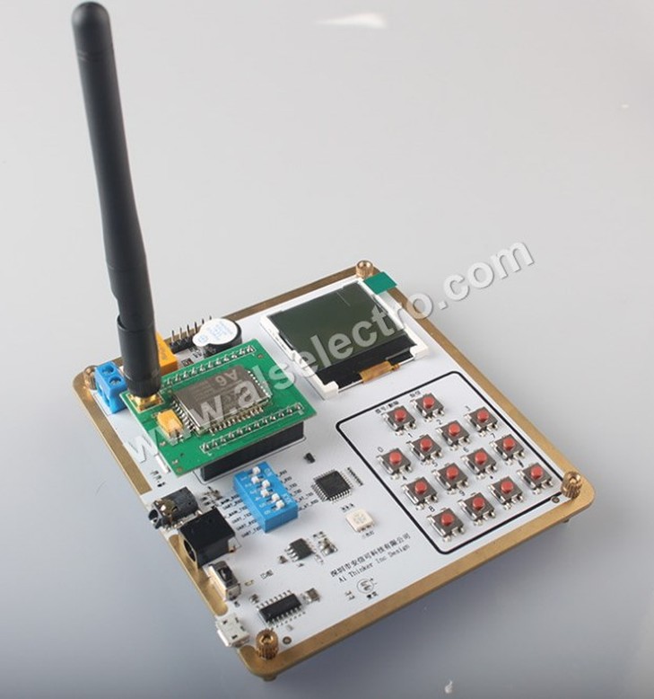
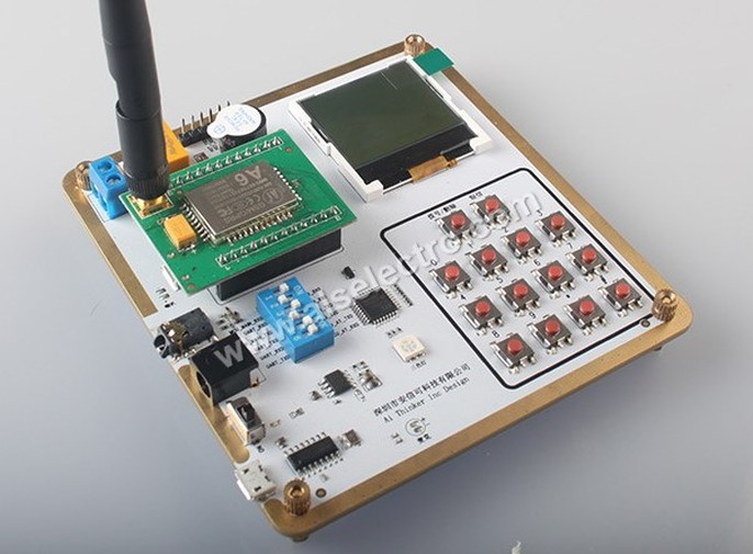
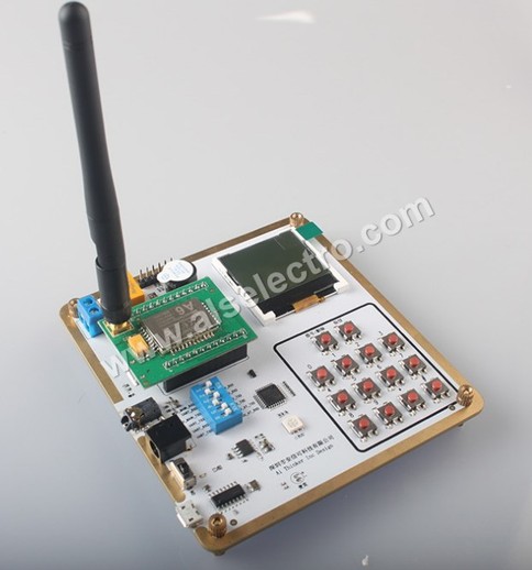
The full DEMO kit of A6 GSM has an onboard CH340 IC for serial to USB functionality .A keyboard , an LCD , relay & buzzer are also provided.
An MCU of STC 8051 family is onboard which is factory preloaded with demo code.
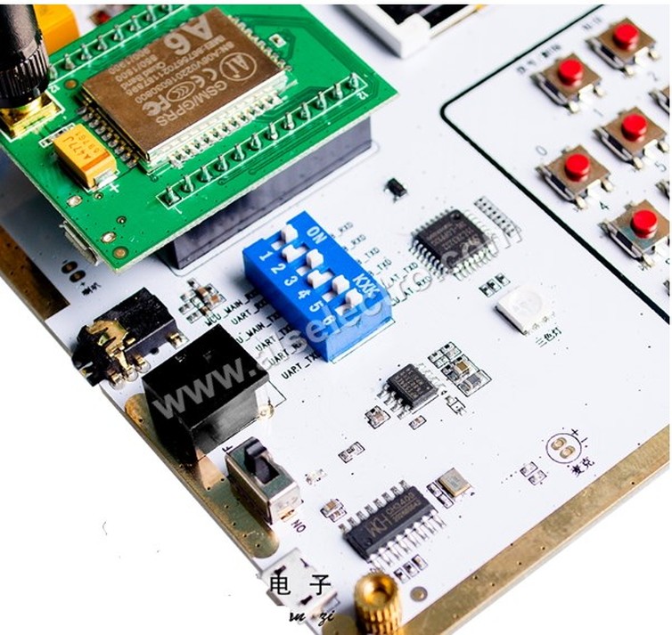
A 6way DIP switch seen near the MCU decides the connection between USB -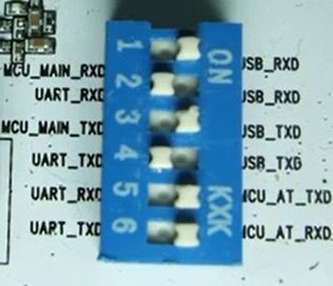
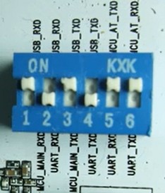
DIP switch description
MCU_MAIN_RXD 51 microcontroller serial download RXD
MCU_MAIN_TXD 51 microcontroller serial port TXD download
MCU_AT_RXD 51 microcontroller module RXD connection A6
MCU_AT_TXD 51 microcontroller module TXD connection A6
USB_RXD microUSB-
USB_TXD microUSB-
TXD UART_TXD A6 module
RXD UART_RXD A6 module
Insert a valid SIM to the back of A6 module & plug it on to the development board.
Set the DIP switch 1,3,5 & 6 to ON position.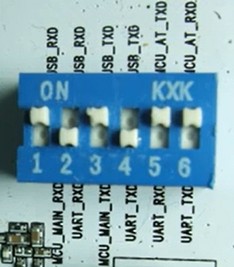
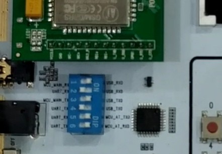
Connect the USB cable from A6 board to PC.The CH340 driver to be installed in PC & in device manager note the COM port alotted.
Provide a 5v 2Amp adapter to the power socket.
Open the serial monitor like PuTty , provide the COM port number & set the Baud Rate to 115200.
Switch on the power.
The boot process takes 5 to 10 secs & finally you get CREG 1
After this the on board MCU will try to connect to AI THINKER cloud.This is a factory loaded demo program.Exact details are not provided by the company.
Wait till this process ends & then type AT .
The A6 module will respond with OK.
To dial a number use ATD followed by number to be called. A semicolon is not needed at the end as in SIM900.
To send a message
AT+CMFG=1 to set Text mode
AT+CMGS="phone no."
Now you get a > symbol.
Type in the message to be sent & press CTRL+Z to send the message.
The phone no. can be dialled from the on board keypad & then press the DIAL button on the top.
To delete number or to provide backspace long press the dial key.
To send a preloaded test message press the Send SMS button seen next to Dial.
.
Now set the DIP switch position 2 & 4 to ON.
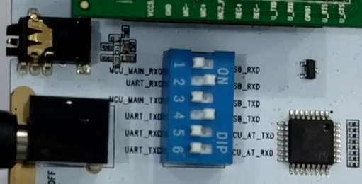
Use the TERMINAL software as it has SET MACROs facility to append 0D (carriage Return) after the AT commands.
Watch the video at bottom for full demo.
Module specifications
Dimensions 22.8 × 16.8 × 2.5mm; Operating temperature -
Operating Voltage 3.3V-
Standby average current 3ma less;
support the GSM / GPRS four bands, including 850,900,1800,1900MHZ;
GPRS Class 10; Sensitivity <-
support SMS text messaging;
Support GPRS data traffic, the maximum data rate, download 85.6Kbps, upload 42.8Kbps;
Supports standard GSM07.07,07.05 AT commands and extended commands Ai Thinker;
supports two serial ports, a serial port to download an AT command port;
AT command supports the standard AT and TCP / IP command interface;
support digital audio and analog audio support for HR, FR, EFR, AMR speech coding;
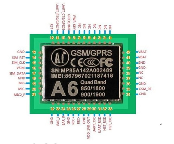
Pin Description
Pin Number Pin Name Explanation
1 to 7 NC Reserved
8 PWR_KEY Power button, 1.9V More than 2s To boot
9 GPIO1 / INT Module for controlling whether to enter a low-
Note that in this mode can not use the serial port
10 UART_CTS / GPIO5 AT Serial ports CTS
11 UART_RTS / GPIO7 AT Serial ports RTS
12 RST Module Hardware RESET Feet, when using this pin low 0.05V, Current 70ma about, Recommended NMOS to control
13 GND
14 SIM_RST SIM card RST
15 SIM_CLK SIM card CLK
16 VSIM SIM Foot Power
17 SIM_DATA SIM Data
18 GND
19 MIC-
20 MIC + MIC positive electrode
21 MIC2_P headset MIC interface
22 GND t
23 EAR_L Headphone left channel
24 EAR_R Headphone right channel
25 GND
26 REC + Speaker positive
27 REC-
28 GND
29 VDD_1V8_OUT foreign 1.8V Foot Power
30 UART_TXD AT Serial ports TXD
31 UART_RXD AT Serial ports RXD
32 HST_RXD Download Serial RXD
33 HST_TXD Download Serial TXD
34 GND
35 GSM_RF Foot antenna, the antenna can be connected, if connected PCB On line, Note PCB On using 50 Ohm trace
36 GND
37 NC Reserved
38 NC Reserved
39 GND
40 GND
41 VBAT Then external power supply pin 3.3V-
42 VBAT
AT COMMANDS PDF
VIDEO DEMO :